need help / new kingpin kit / no instructions / pic for reference
#1
 08-01-2009, 08:38 PM


need help / new kingpin kit / no instructions / pic for reference
I just picked up a new kingpin kit from DC and there were no instructions in the box. I've got a few pics from when I took the old one out and fairly clear on reassembly however there are a few items I need to make sure I get in the correct sequence. Can you look at the pic below and help me determine where the 4 items at the top go? The top item is a very thin washer shrinked wrapped to the piece of cardboard. The next row are recessed and appear to hold the felt rings on the 3rd row. The 4th row are some type of bearings. The remaining items I am confident I can reassemble correctly but I need your help with the top 4. Thanks for the assistance.

PS. I could really use some suggestions on getting the new bushings inserted in the spindle but that may be the subject of another post unless anybody wants to take a swing at it now.
PS. I could really use some suggestions on getting the new bushings inserted in the spindle but that may be the subject of another post unless anybody wants to take a swing at it now.
The following users liked this post:
#2
08-01-2009, 10:44 PM

Post Fiend
The following users liked this post:
#3
08-02-2009, 09:53 PM
Thanks Julie. I've got a manual and the three diagrams for spindles seem to start at the 500 series and go up from there. What I had(have) most closely resembles Fig. 5 for the 500-600 series but not identical. The 4 parts I was looking for help on appear to be the spindle bolt retainer, dust washer, spindle bolt bearing assembly, and a washer type item I have in the kit but do not see in the diagram. Plus it's hard to tell the dust washer & spindle bolt retainer from each other in the pic. The felt piece I mentioned looks like a spindle oil seal from Fig 6 on the 700 series. I was just looking for some assistance to make sure I got the parts pictured from my kit in the proper sequence once I reassembled. I didn't mean to suggest someone recreate a set of instructions that was already available in the manual. Blame it on my poor comm skills and public school edumacation.  My goof.
My goof.
The following users liked this post:
#4
08-03-2009, 01:22 AM
Senior User
I have a PDF but don't think I can attach it...here are the instructions in writing.
Note: the washers in the cardboard are shims...see step #8
KING PIN REMOVE/INSTALL
1. Remove wheels, tires, steering arm and brake
components from spindle.
2. Remove nut from kingpin lock bolt and drive out lock
bolt with a brass hammer or drift. Remove grease
zerks.
3. Working from the bottom of spindle, use a hammer
and suitable drift to drive kingpin up out of
spindle/axle. Remove spindle noting the location of
the thrust bearing and / or any shims (if used) to
ensure proper reassembly.
NOTE: If kingpin is
seized in axle and cannot be driven out, soak with
penetrating oil and try again in 24 hours. If still
unsuccessful, remove the axle assembly from
vehicle and have kingpin pressed out. It is not
recommended to use heat to free kingpin from axle
boss. Excessive heat can deform or embrittle the axle
boss and spindle.
4. Thoroughly clean and inspect spindle and axle for signs
of damage, scoring, or cracks. The new kingpin should
be a snug fit in the axle bore and not have any play.
If it is tight the bore can be cleaned up lightly with a
brake hone. If there is excessive play the axle will
have to be removed and reamed for oversized kingpin
and bushings
Replacement of the bushings requires
specialized equipment. The bushings must be reamed to
final size after installation. It is recommended that the
spindles be taken to a competent machinist for this work.
5. Using a suitable arbor, remove old bushings and press new
bushings into the spindle, aligning the grease hole of the bushing with the grease zerk hole in the spindle. Incorrect installation of bushings will cause premature wear of kingpin and bushings. (use a machine shop!)
6. Align hone / ream both bushings in unison for a final clearance of .001” to .0015”.
7. Pack new thrust bearings with quality bearing grease. Install new grease zerk fittings.
8. Insert old kingpin up through lower arm of spindle approximately 1". Install the thrust bearing on
kingpin with metal dust shield up toward the bottom of axle boss. (Some applications may require a
spacer on top of the thrust bearing). Position spindle on axle, sliding kingpin up into axle boss.
Measure clearance between the top of axle boss to under side of upper arm of spindle. If gap is
greater than .015” add shim(s) as necessary to obtain proper clearance (.005" - .015").
9. Install cup washer on kingpin with flat side against head of kingpin. Place felt washer on kingpin and
slide up into open side of cup washer.
10. Orient notch of new kingpin toward center of axle and push kingpin down through shims and top
arm of spindle, aligning the notch in the kingpin with the lock pin hole.
11. Install lock pin (flat of pin engaged in kingpin notch) and nut. Torque nut to 25 ft lbs.
12. Repeat for other side of vehicle.
13. Install steering arms, brake components, wheels and tires.
14. Grease spindle bushings and perform front end alignment.
The following users liked this post:
#5
08-03-2009, 01:31 AM
Post Fiend
The following users liked this post:
#6
08-03-2009, 09:02 PM
The following users liked this post:

#8
09-10-2010, 01:08 PM
Post Fiend
Just a couple of caviats that you may not pick up on in the pictures.
The Spindle Bolt Thrust Bearing (P/N#3123) has two surfaces - one is flat and the other has the bearing case sides rolled up and over to from the other surface. If you look at it you will see what I mean.
Anyway, the flat surface goes DOWN.
Your all welcome btw - good luck!
The Spindle Bolt Thrust Bearing (P/N#3123) has two surfaces - one is flat and the other has the bearing case sides rolled up and over to from the other surface. If you look at it you will see what I mean.
Anyway, the flat surface goes DOWN.
Your all welcome btw - good luck!
#9
09-10-2010, 04:28 PM
Cross-Country
press fit
If you don't have a hydraulic press, the bushings can be drawn or pulled into the fit with a piece of all-thread, washers, and nuts. It's very easy to do. You'll just need to make sure the grease holes are aligned. Afterward, the bushings will need to be bored to the king pin O.D. +.001-.002. It is trial and error, unless you have inside and outside micrometers. It is correct to use a reamer, if you can get one. Good luck.
The following users liked this post:
#10
09-10-2010, 04:32 PM
Cross-Country
The following users liked this post:
#11
09-10-2010, 06:21 PM
Post Fiend
I took mine to a machine shop and for $50 the reamed and wet honed the kingpin bushings to the exact size needed. But I wanted to make sure it was done right and tight and I've never done it before.....So........
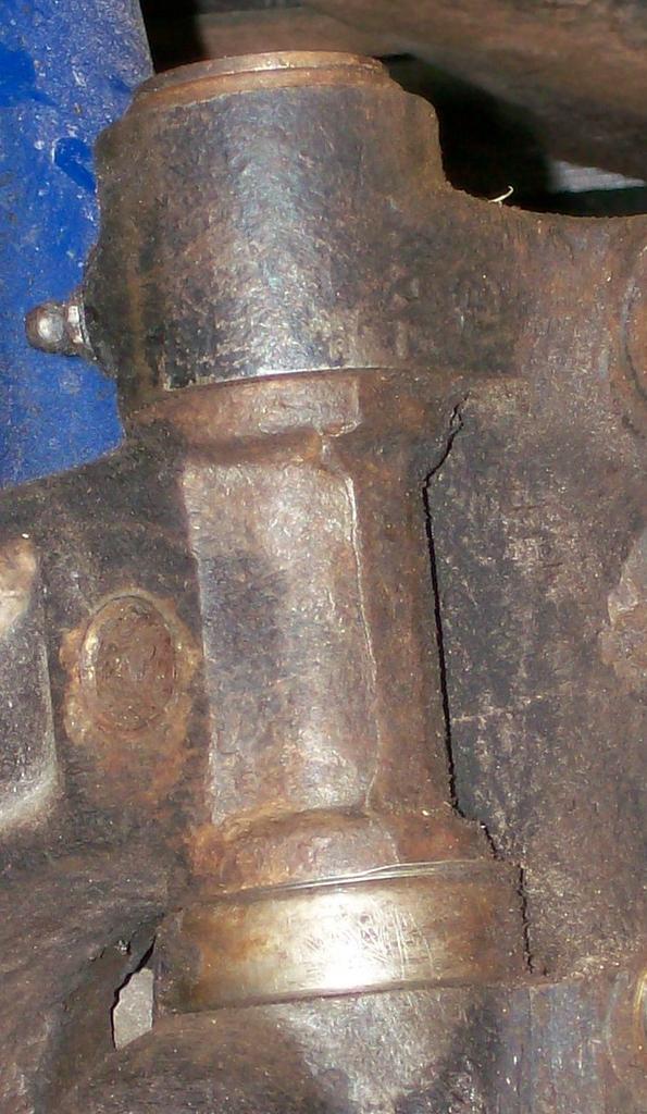
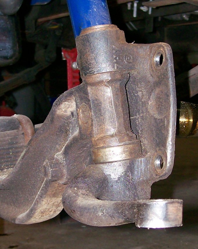
Only one shim? That's pretty amazing. Mine took three on either side. You can see them in the the (before) pictures. I think (at least mine did) the kit comes with 6 shims. If not all the resto parts shops carry extras.
Only one shim? That's pretty amazing. Mine took three on either side. You can see them in the the (before) pictures. I think (at least mine did) the kit comes with 6 shims. If not all the resto parts shops carry extras.
The following users liked this post:
#12
09-10-2010, 08:55 PM
Cross-Country
The following users liked this post:
#13
02-19-2011, 05:26 AM

LMC king pin kit
So here is the kit from LMC and I'm wondering if anyone knows what the pieces in the lower left corner are for as they do not look like any of the OG parts. also the kit does not have felt washers or "caps" to hole them either. it has some small washers with some rubber inside of them like a seal.
Any thoughts?
Daniel
The following users liked this post:
#14
02-19-2011, 08:21 AM

The following users liked this post:
#15
02-19-2011, 08:30 AM
Well that sucks then, It appears that I ordered the right part number from LMC 45-2750 48-52 F1 & F2, recieved the right box but had the wrong contents in it! Got to love that...
I got the whole axle and spring removed and the wrong parts, now they tell me to call them back Monday. I guess one is bound to eventually have a problem with every vendor when you use all of them all the time.....
Daniel
I got the whole axle and spring removed and the wrong parts, now they tell me to call them back Monday. I guess one is bound to eventually have a problem with every vendor when you use all of them all the time.....
Daniel
The following users liked this post: