When you click on links to various merchants on this site and make a purchase, this can result in this site earning a commission. Affiliate programs and affiliations include, but are not limited to, the eBay Partner Network.
Before you start reading, I want to state just what is contained and what isn't in this write-up:
What was done?:
- Automatic hubs where replaced with Warn manual hubs
- Bearings and seals in the hubs
- Brake rotor and pads
- Inspection of the front axle u-joints
What wasn't?:
-Replacement of the bushings, ball-joints, drag link or anything else related to the steering.
Of course, all of this was done to the Dana 44 TTB that's installed in my 1993 Bronco.
Ok, let's get started:
I have been having several issues with the truck lately, my brake pads were worn enough to scratch the rotors, which were already too thin to be turned, there was also this regular chirping noise from the passenger's front wheel when the truck was moving (possibly a worn or dry bearing) which increased noticeably if I drove through any water, finally, the front axle u-joints looked very dirty and since they aren't greaseable, I decided to inspect them, so it was time to work on the bearings and brakes, the u-joints and the manual hubs were extras I decided to do since I was going there already, the ball joints were too expensive and I didn't have any good brand available so I decided to left them out of this rebuild, but if you're going through all this hassle, I would advice replacing them.
Tools required:
Again, I work with what I have at hand and basically in the street, if you have other resources that will make things easier, by all means!.
- Protective gear set: Eyewear and gloves of your choice, but wear them.
- A Jack.
- A Grease gun (packed with quality grease, I used Castrol Synthetic grease).
- One jack-stand.
- Two Lug wrenchs (one cross type to dismount the tires, and a single bar type to use as a lever).
- One C-clamp (6" minimum).
- A rubber mallet.
- A pair of needle nose pliers.
- A medium sledge hammer (2.5-3lbs).
- One punch.
- A Torquimeter (anything that reaches 200lbs/ft will do).
- A Breaker bar (1/2 coupling)
- A screwdriver with interchangeable tips.
- A set of Torx tips.
- A set of socket wrench and sockets with a 3" extension (most of the ones I used were 3/8 couplings and some 1/2).
- One socket big enough so it can receive the u-joint cap loosely, but small enough to have a good hold on the yoke (I used a 1 1/4).
- A short extension for the torquimeter (probably a 1/2 coupling).
- Finally, the only special tool required: a Spindle nut socket for Dana 44, there are two kinds of these, I was only able to find the one with the outer teeth, like the Powerbuilt 648473. The best type is the one like the AC675, which will have inner teeth with a skirt that will prevent the tool from slipping out when you're applying any important torque to the nut (of course I was only barely able to find the inferior type, a Cal Van brand one).
Most of the tools assembled before I started working.
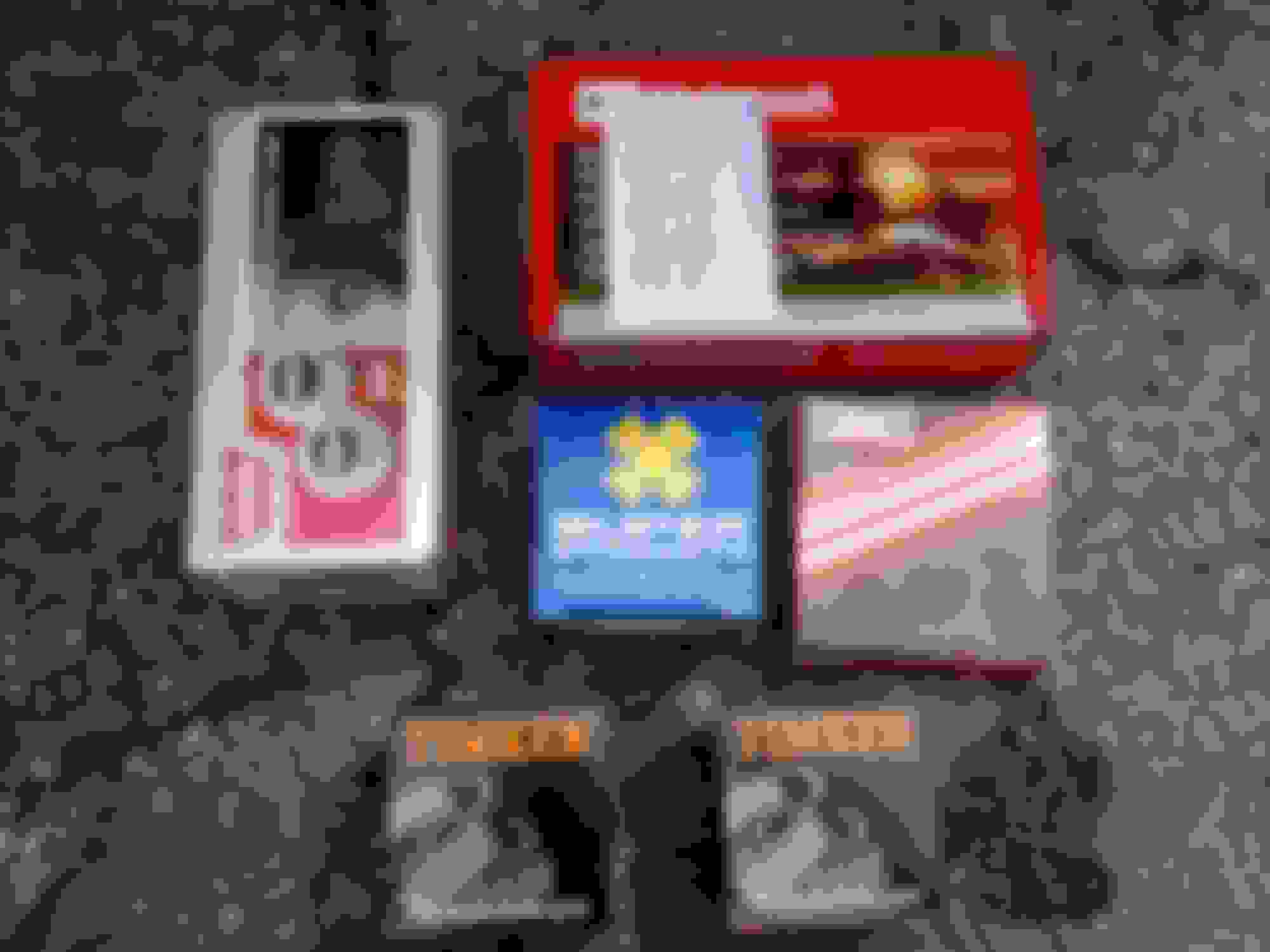
The Spares:
- Warn manual locking hubs (I was unable to get Premiums, but I'm happy regardless...).
- Timken bearings: SET 37 and SET 45 (smaller one), two of each.
- Motorcraft Brake pads (the ones in the picture were actually wrong, I had to return them, but I did use the proper Motorcraft ones).
- Venezuelan brand Rotors.
- Precision 371 super strenght u-joints (again, the 377 will also fit and they're greaseable through the caps, I was unable to find them or the Spicer 570x which were my two preferred choices).
- Assorted seals and gasket for the Dana 44: get some good ones, they protect everything from the water and retain the grease inside.
- I replaced another bearing... a small one in the passenger's side spindle, I just can't recall the number (size).
Some of the replacement parts... Shiny new parts make Encho very happy!.
The procedure:
As usual, a flat, clean surface would be very desirable to work.
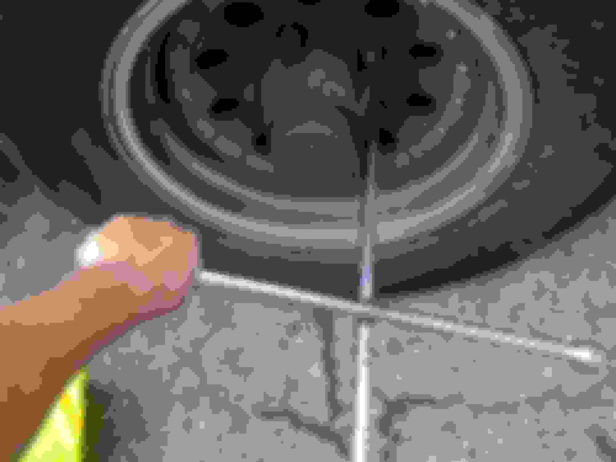
The first step, is getting the tire out of the way, of course, to do so, start by loosing the lugnuts using the lug wrench, then, use the jack to lift the axle (be careful of the supporting points you pick, and keep in mind you need to place the jack-stand, so leave room for it). Once you do that, remove the nuts and place them somewhere safe then take off the tire (you can use it as a seat if you desire).
How to loose a tight lugnut and not break anything (in your body): don't pull!, use your body weight over your left arm, placing the wrench like shown, do little "jumps" until the nut becomes loose.
This is the proper spot for the Jack-stand.
Once everything is secured and the tire out of the way we can start working, removing the old auto hub is the logical next step, that and the old brake pads.
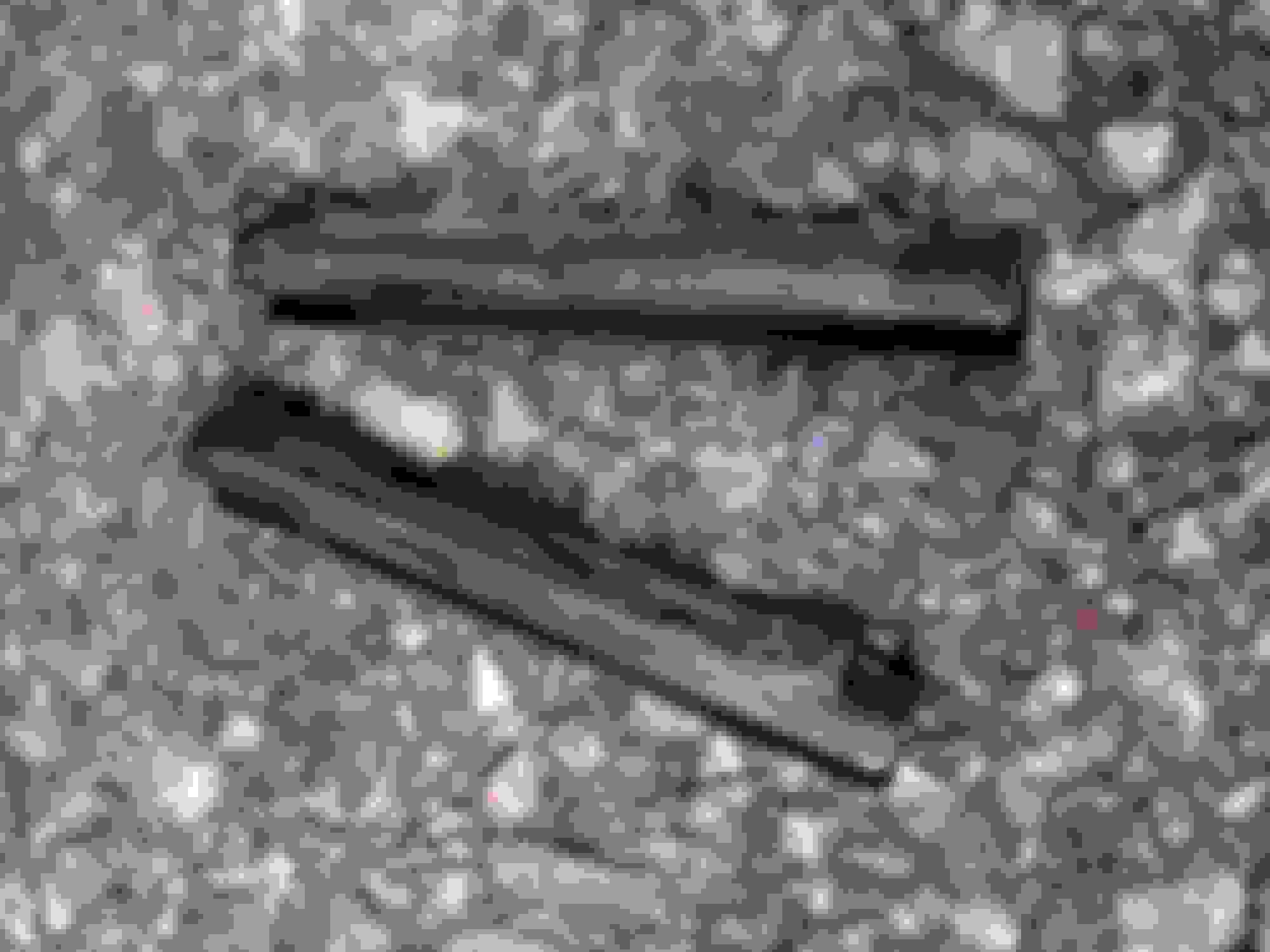
Removing the brake pads is extremely easy if your truck has the wedge pins (a rubber piece with 2 metal plates), if not, you have to take a couple of bolts then slide out a metal retainer. Since I have the wedges I will explain that procedure: There are 2 pins holding the caliper in place, take the punch and place it on the vertex of one of the steel plates in the wedge (start with the lower wedge), then tap on the punch with the hammer until the pin goes out completely on the other side (they will give a little resistance, then will slide out easily, I started them with the 1/2 extension), then repeat with the upper one, once they're out, tap on the caliper with the hammer if it gives you any trouble to come out, now you have access to the brake pads.
Starting to push the wedge using the extension, remember, just tapping.
Punch and hammer, notice the lower wedge inside already, ready to be "punched-out".
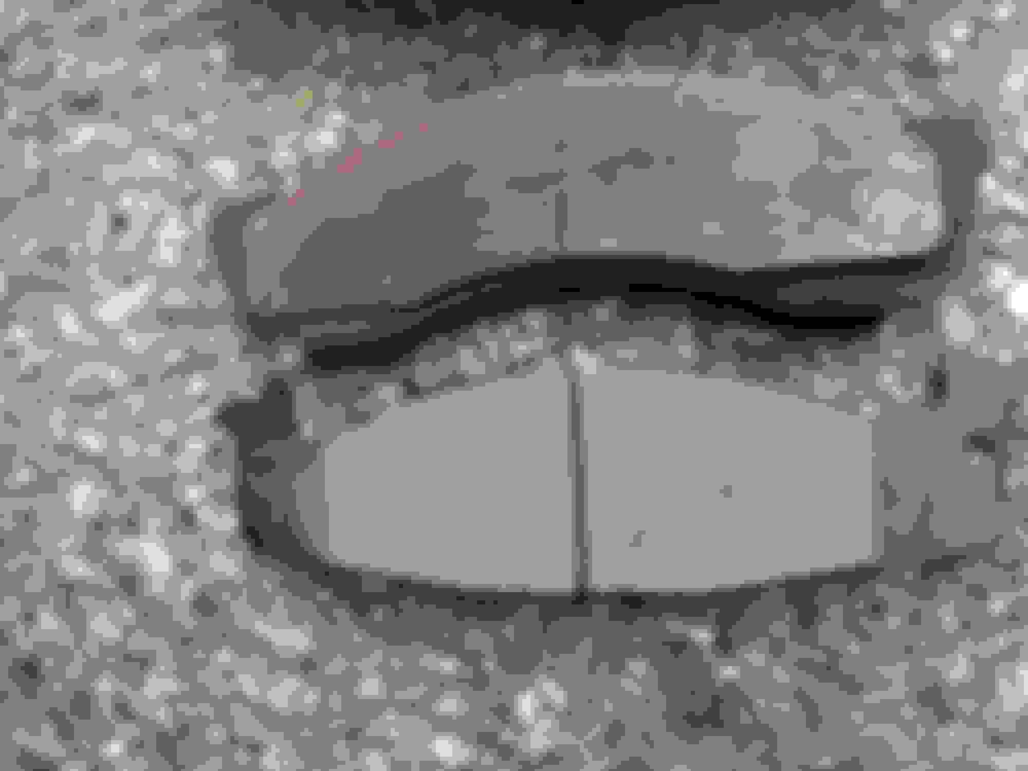
These are the wedges, they only go in one way, so you won't mess anything here. Remember to clean them and lube with brake grease upon installation.
Calliper out, just hit the pad with the hammer and it should come out if it's being stubborn.
Old vs. new... aaaaand back to the store... lovely when it's the only car you have available...
Anyway, I just left the calliper hanged from the radius arm and moved on (Don't ever let the brake lines hold the weight!)
Automatic hubs extraction:
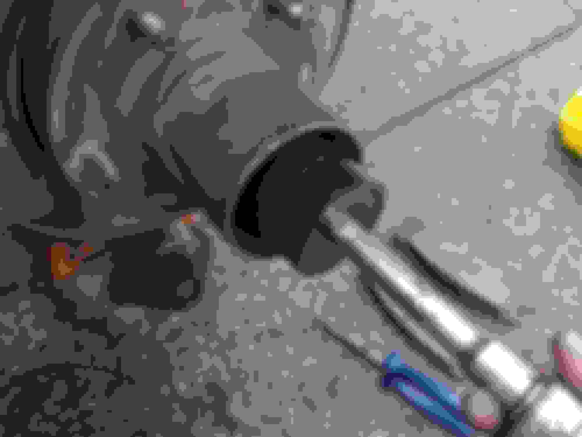
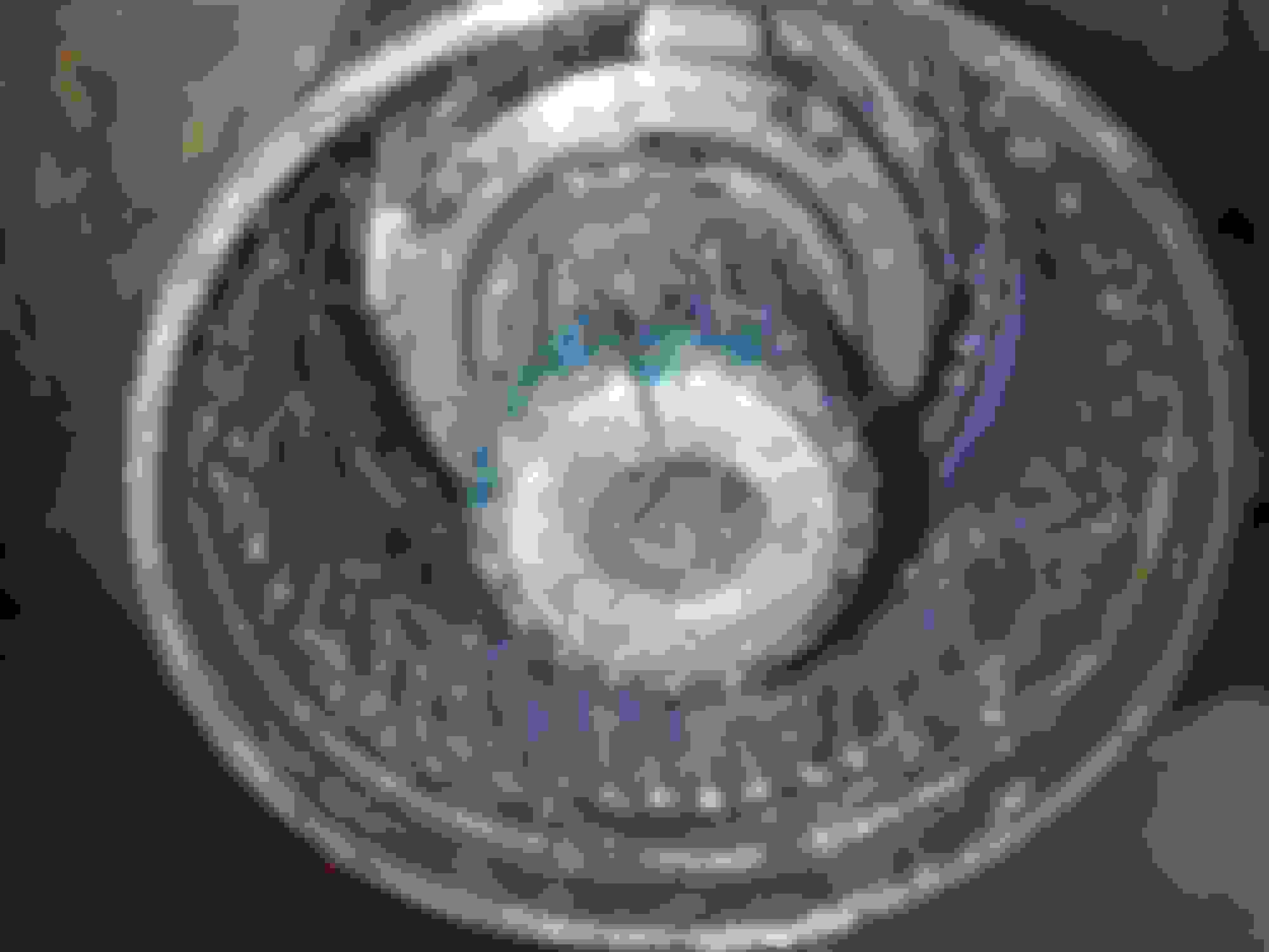
Anyway, now is a good time to take the auto hub out of the way and ready to be replaced, take the hub cap out (a T20 Torx tip will fit the 5 bolts if memory serves), then take the little cap, bearing and spring in the center of the hub, remove the little square cap on the top, then you'll be ready to take the hub body out, to do so just follow the instructions posted on each picture:
Using the pliers, grab on both these pins, they're actually the ends of the safety ring that fits the grove around the hub body and keep it in place, pull them together then pull out the body, it might slide a little, once the ring is out of the groove it fits in you can use one or two of the cap bolts in the hub body to help pulling it out. The red RTV was a futile attempt to stop the grease from escaping through the hub cap.
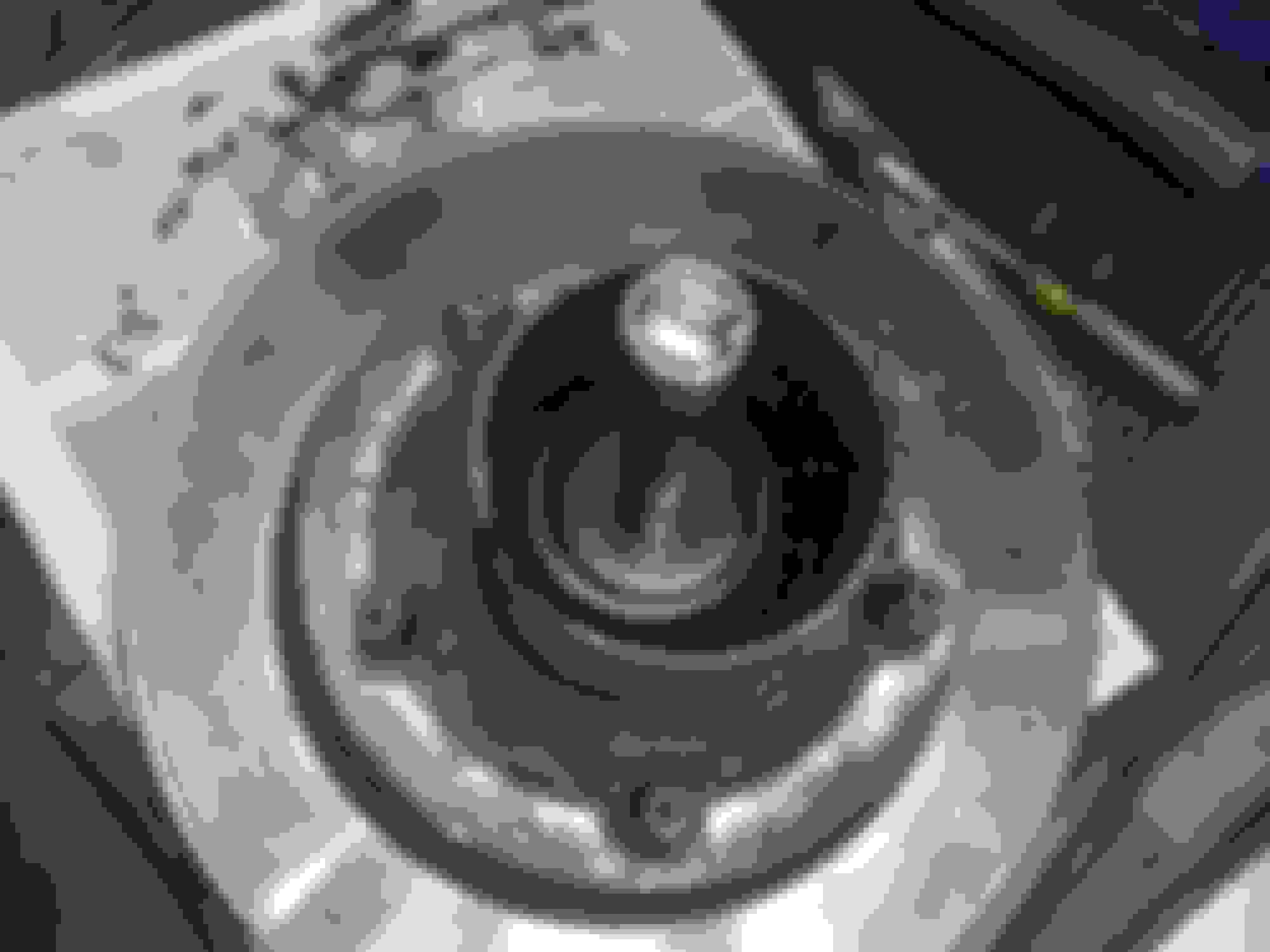
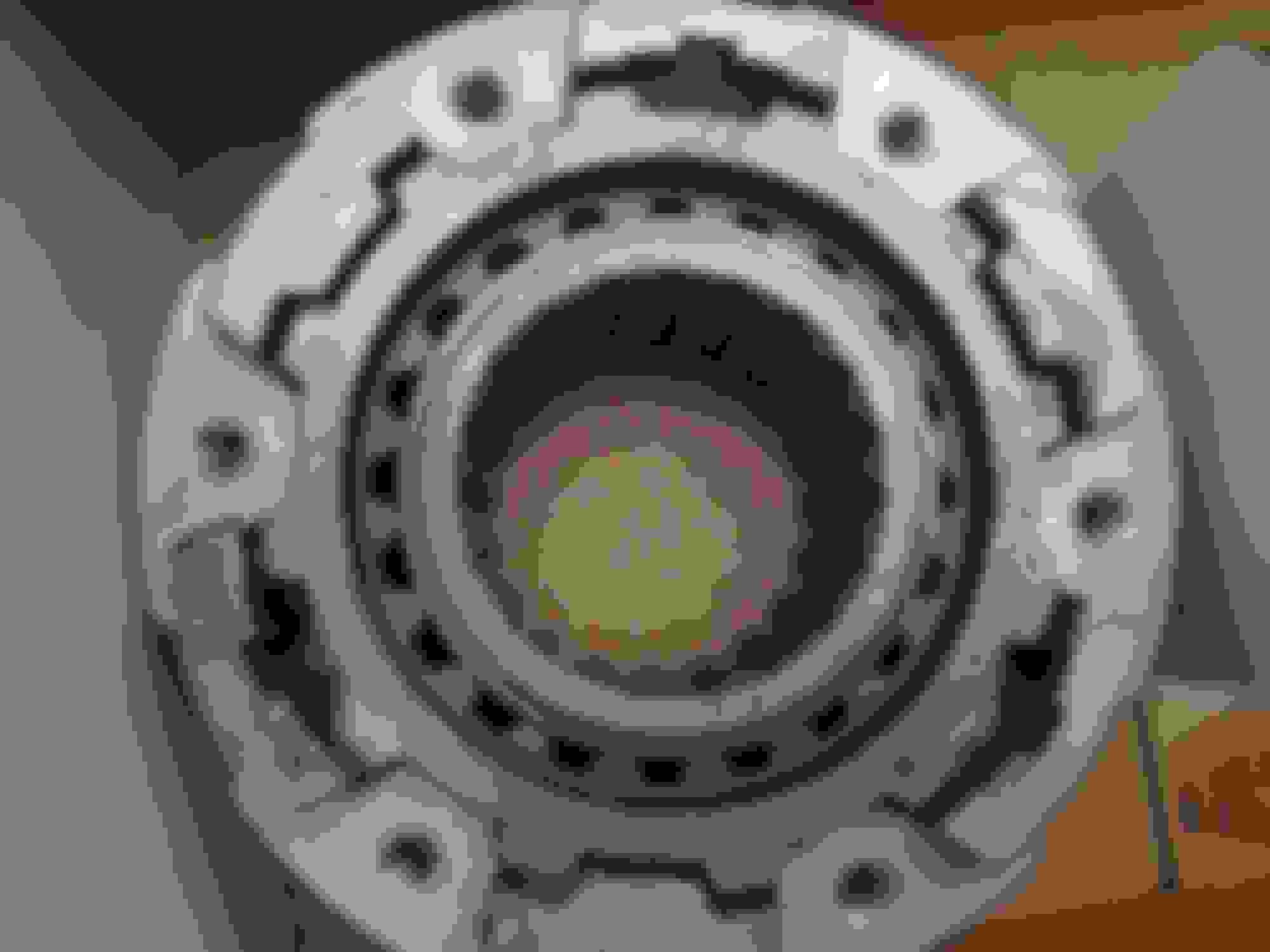
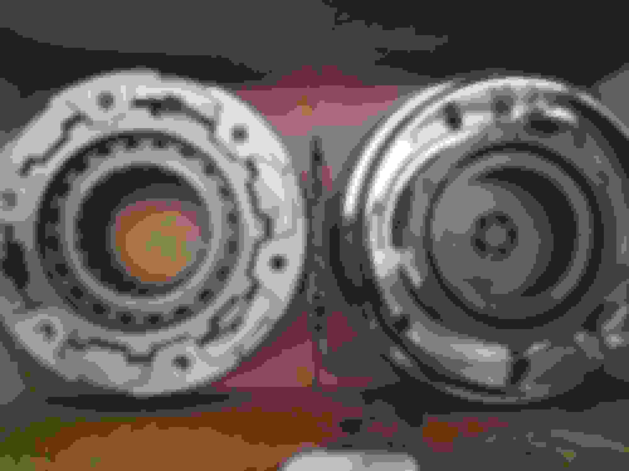
Here is the auto-hub body out (good service... but good riddance!), now you can see the real shape of the ring and how it works.
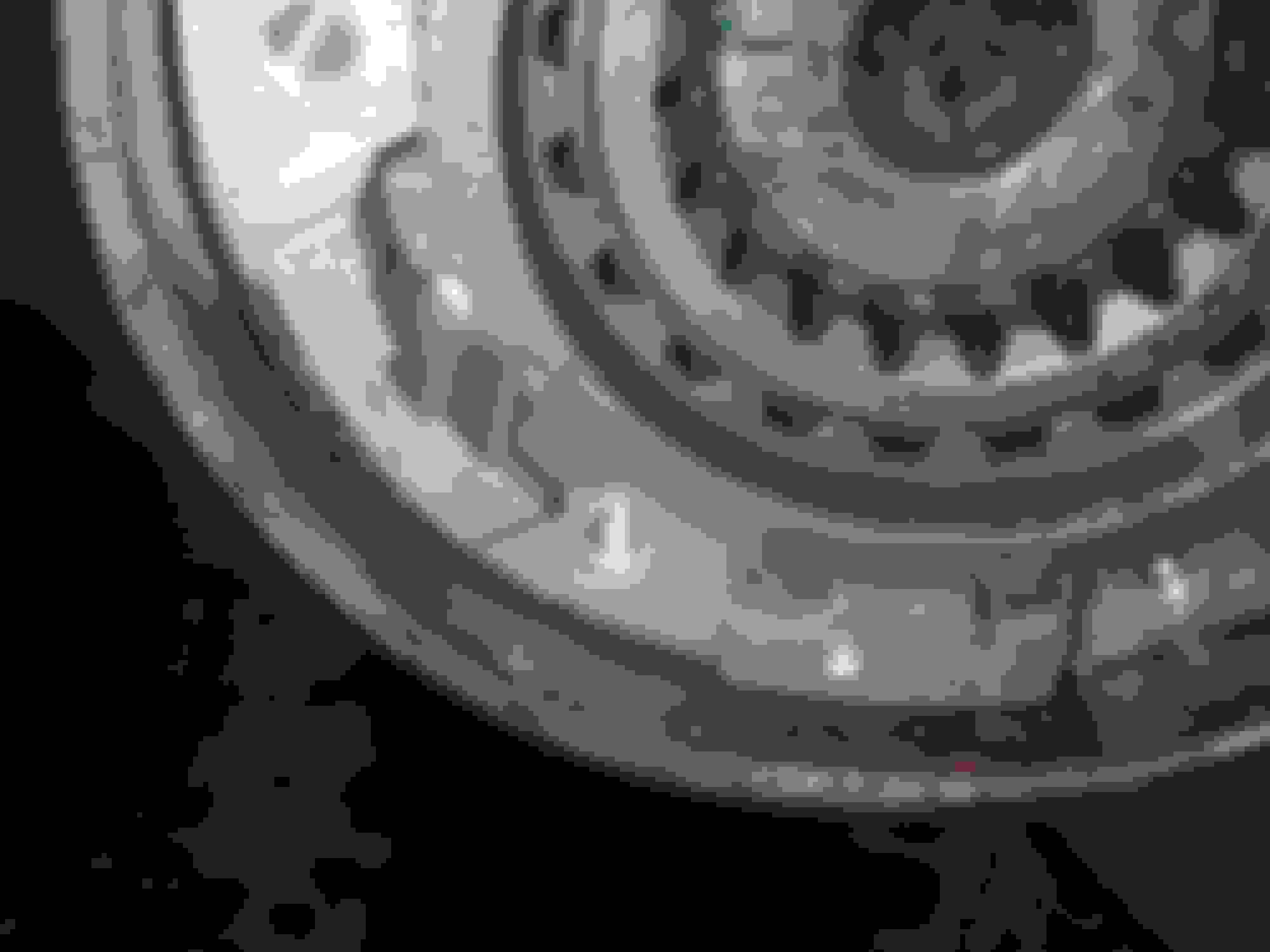
Now it's time to remove the C-clip behind the hub body, it will turn, but it won't slide out (can't be just pulled out of the hub), using a screwdriver (or two) pull it out of it's groove in the axle shaft then grab it, sorry, no pic (but check the next one for a clue).
If you look closely you'll notice the groove for the C-clip in the shaft (in the back), next in line is the splined spacer/washer, just pull it out, the shaft groove might bother you a little, just match the splines and pull again.
Pulling the splined spacer/washer out.
This pretty much covers the extraction of the auto-hubs, if you were only interested in replacing the hubs go to the "Manual Hubs installation" section near the end of the write-up.
Now it's time to take both spindle nuts and the safety washer between them off. Grab the breaker bar, the 1/2 extension and the spindle nut socket. Using just the extension on the socket, insert them inside the hub and turn them slowly until they engage the outer spindle nut, then attach the breaker bar to the extension and turn CCW until the nut comes out. The safety washer has to be pulled from two opposing points in its diameter to come out easily (inserting it back is what's a pain). After the washer is out, you can take the inner spindle nut out, just repeat what you did with the outer nut.
The spindle nut socket in place. I was able to use my 1/2" socket wrench instead of a breaker bar to easily drive it out because the last idiot that worked on the truck used a screwdriver and a hammer to remove/insert the spindle nuts (you'll see), I was basically driving on lent time safety-wise.
Look at this spindle nut, this is how all these idiots hurt it using hammers and chisels, and every single spindle nut looked like this.
Now that the spindle nuts are out you will be able to take out the hub to take off the brake rotor and replace it, which is quite easy, it might look like they're welded in place, but hit the studs with the hammer and they will pop right out the back, as always, take due care, set the new rotor in place and hammer the studs back in (if you purchased new studs... you know the drill). Depending on the condition you received them in, the new rotor could require being turned before the installation (mine were fine, so they went right in).
You will also be able to inspect or replace any of the 2 bearings inside the hub. To extract the bearing races you will need a hammer-type bearing extractor, which I didn't have, and since the races were in great condition I decided I wouldn't get in the trouble of taking them out, the bigger bearings are very easy to replace, the outer one is the Timken SET 45 if memory serves (SET 45 is actually smaller than SET 37), to access the inner bearing (SET 37) you need to take out the rear seal, if you do it carefully enough, you will be able to re-use it but I replaced it along with all the bearings because this side was the one that made the noise, so the seal wasn't doing its job and the bearings, even though they had grease, showed signs of rust.
Take the bearing out of the way, then, use the socket and extension to pop out the rear seal, again, the hammer is your friend. This is also the proper position to hit the studs out when replacing the rotor.
We can now get the spindle out to get access to the axle, to do so, the first step is taking the housing of the ABS sensor that overlays the spindle and said sensor out of the way, behind the spindle you'll find the bolts (2) holding that assemble to the knuckle, take out the upper one, then slide the sensor (a little cylinder) out of the housing, then the second bolt, by now you should be able to take the sensor housing off the spindle. Once this is done, take the nuts out to release the spindle, once the spindle is out, check the spindle's rear bearing and replace the seal. My spindle bearing was rust/dirt shut, and probably the cause of the chirping noise, so I replaced it.
The spindle, notice the sensor/housing just beside the spindle stud (the one without nut), just my luck, as I got here it started raining heavily, hence the wet spindle.
This is the rear of the knuckle, showing the bolts for the sensor housing, this is the best image I could get, sorry if it's a little confusing.
With the spindle out you can access the axle, notice the housing of the sensor that held the spindle to the left.
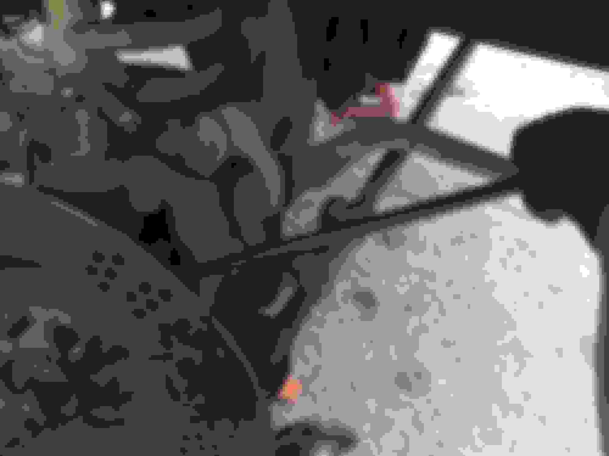
To take the axle out, you'll need to get under the truck, in the passenger's side axle, to release the rubber boot, once this is done, you can grab the axle where the spindle was and pull it out. If the yokes give you trouble going through the knuckle, you could try prying them out carefully with a crowbar or any other tool that you can place there for leverage:
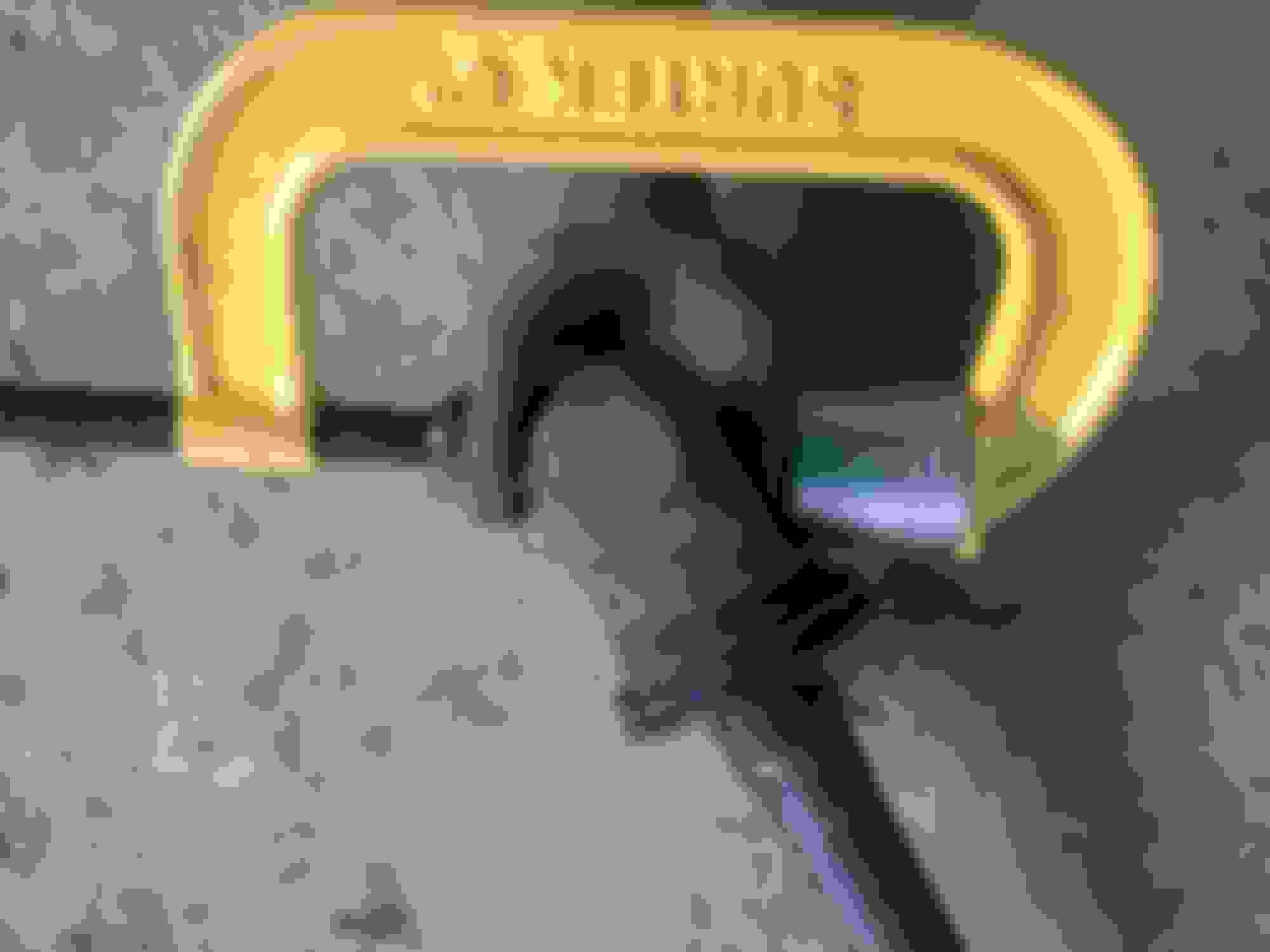
Using the original lug wrench of the truck to pry the yokes through the knuckle, once it was set like this I just pushed until the axle popped out. Notice the yoke almost outside already, and more seals to replace, these mate with the ones in the spindle, supposedly sealing the whole assembly.
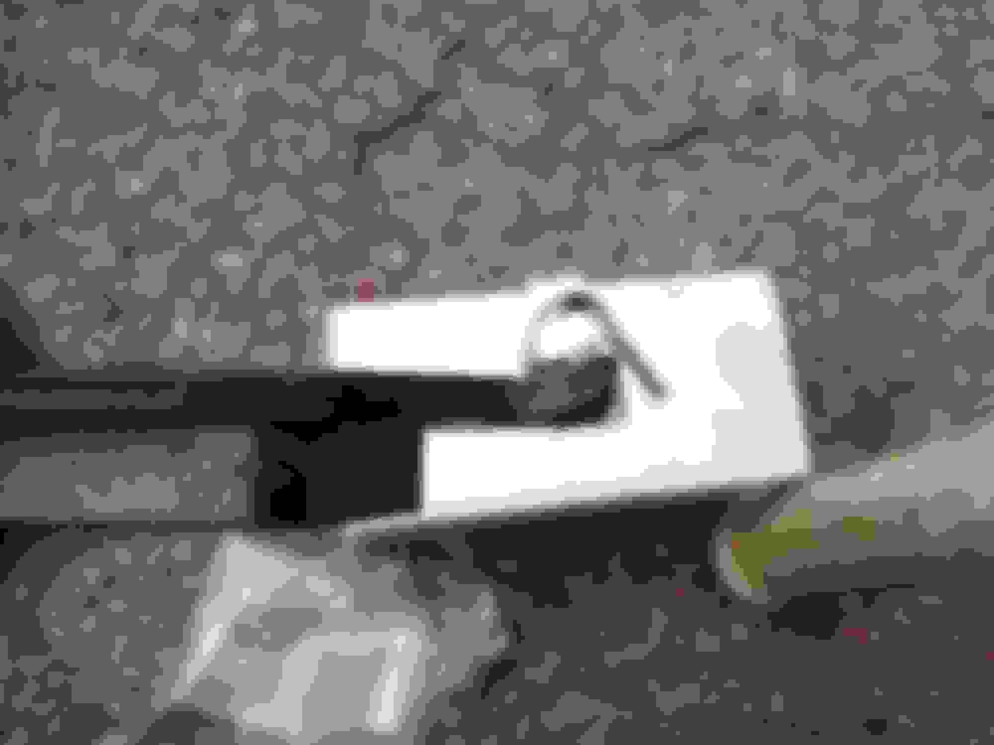
The inner end of the p's side axle, once again I pay for the mediocrity of another hack. The rubber boot was never tightened and water got inside, rusting the splines; anyway, I brushed the rust away, used rust cleaner, dried them out, then packed them with grease before installing the axle back.
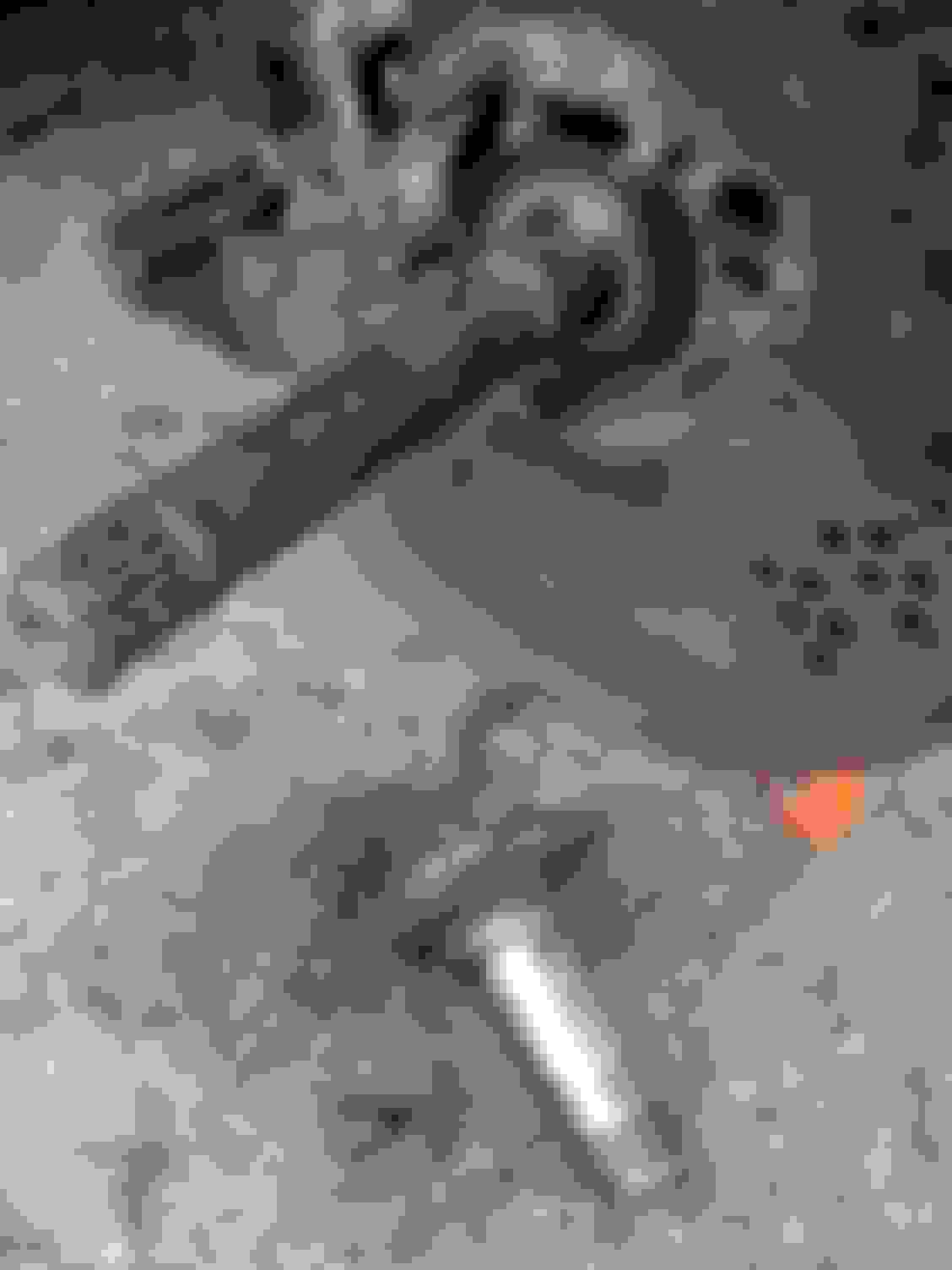
Another picture of the axle, getting ready to check the u-joint.
Upon testing, I found both u-joints to articulate and turn very well (mostly cosmetic crud outside, they remained lubbed inside), with zero play, and decided against replacing them, anyway I'm ready to do it if needed.
As I already stated, the u-joints were fine, so I left the old ones installed, anyway, if you need to replace them, this method should work on the trail (requires light tools you can actually carry around when taking a trip): first, remove any snap rings or retainer clips the u-joint has (usually located in either end of each cap), then, using the C-clamp and the big socket place both in one of the axis of the u-joint, cupping one of its caps with the socket and setting the clamp's screw against the other, find some place suitable to work preventing the axle from rotating when applying any significant torque, then turn the clamp's screw until the u-joint unsettles from the yoke, keep turning until you are able to remove a cap, repeat this procedure on both axis of the u-joint and voila!, the u-joint is out. To install the new u-joint you can insert it in the yoke with one cap on, then use the clamp again but with a small socket* (roughly the same diameter as the cap), to push the other cap and press the whole assembly together, and then insert any retainers the new u-joint has.
If by some chance the old u-joint won't budge, try wd40 or any other penetrating product and a hammer with a small socket* and hammer away, but this method could hurt the yokes, the socket, or you (if any metal chips OR the hammer hit you) and will definitely hurt the u-joint, and could also hurt the yokes or the axle, this is a last resort.
Getting ready to extract a u-joint on the trail, if there isn't a press available this is how the C-clamp and socket should be set against the yoke. Personally if there is the slightest possibility of using a press or doing this repair later in town, I advice against the aggravation of trying this approach.
Assembly procedure:
At this point, if you wished, you could work on the ball-joints very easily, but since I didn't do that, we can start the re-assembly, basically you'll be doing the opposite of what we have done so far, lube the splined surfaces with grease and insert the axles (if the yokes give trouble again you can tap on the axle with the hammer until they clear the knuckle), then mount the spindle, installing the nuts and then the sensor housing and the sensor, by now the hub should have new, grease-packed bearings, a new rear seal and a new rotor, once ready, insert the hub in the spindle, taking precautions so none of the bearings/seal move out of place. Once in place, it's time to insert the spindle nuts and the safety washer, you have to do this very carefully and in a special sequence, first goes the spindle nut with the pin, this pin should be facing outside, take the torquimeter and the spindle nut socket with the extension, you should apply 180 lbs/ft to this nut, this is done to properly seat the bearings in the hub, then, loose the nut again and re-torque it to 60 lbs/ft, next is the washer, it has holes around its body and a tab that should be placed at 12 o'clock, the pin of the first nut should be inserted in any of the holes of the washer (this sounds easier than it is), the tab won't allow much freedom to the washer so be aware of that. If the pin doesn't line up with any of the holes, try flipping it. Once the washer is in place, insert the outer spindle nut and torque it to 60 lbs/ft.
With the hub in place, now you can either install the manual hub lockers or the brake pads, I did the later. Installing the brake pads and setting the caliper back in place is very easy, except for some possible minor issues, take the new pads, there should be 4, one to the front (outer) and one to the rear (inner) of each rotor, before mounting any you need to recede the caliper piston, use the C-clamp to do so, if by any chance the piston seems like it's making too much resistance just press the brake pedal softly a couple of times, this should release it, then use the clamp again, be careful of the dust seal (I receded the piston so much it actually grabbed a little of the rubber when I finished the installation... oh well...), now mount the outer pad on the caliper (I hammered a little some of the tabs before until I felt the caliper grabbed it fine) and use the C-clamp to seat it in place, as for the inner pad just place one anti-rattling clip in one of the ends (your pick, but the lower end is recommended) and set it in place (this should be quite easy, the clip acts as a spring, so be careful, press it down and insert the pad in place).
Setting the anti-rattling clip on the inner brake pad.
Another view of the clip in place.
I hammered the tabs of the pad a little for a better fit, you might choose not to use the C-clamp to seat the pad.
Driver's side, the pads and caliper in place, just line up the channels for the wedges and insert them, notice the lower wedge in place, ready to be pushed in. You can hammer it in and then finish inserting it with the punch, you could also lube the wedge with some braking system grease to ease the job.
Manual Hubs installation:
This is rather easy but you have to do it carefully, first the axle splines and hub splines should be properly lubbed, now let's check out the hub's body so you fully understand my instructions:
Everything lubbed and ready to receive the new Warn manual hub locker.
This is the hub's body, it has outer splines (not shown) and inner splines, the trick is to match the inner splines with the axle, then rotate the body to match outer splines with the hub (the truck's), then you should be able to push the body in.
Once the hub's body is partially in use the rubber mallet to push it fully inside like shown.
Once the body is installed, you should be able to see this grove in the hub, insert the supplied retainer ring in there.
Now, here are the main pieces of the Manual hub locker, the body and the cap (which has the dial). Once the body has been installed, all that's left to do is to set the o-ring in the cap and install it, notice the 3 legs in the cap and the matching holes in the body, just match them up and that should be it, use your Allen tip on the screwdriver and tighten the 5 bolts, that's all there is to it!.
This is the lovely finished product, notice there is no gap between the hub (truck's) and the hub locker's cap. If by any chance there is a gap, you have two probable causes: if it's about 1/8", the safety washer isn't properly seated in the spindle nut pin, you know what to do, sorry... If the gap is bigger, check if you inserted the cap's 3 legs in the body (I forgot this and it didn't go all the way in. It as getting extremely frustrating until I noticed...).
When everything is done and said, you just have to mount the tire and that should be it, pre-tighten the lugnuts, then use the jack to remove the jack-stand and lower the tire to the ground, then finish tightening in a cross pattern.
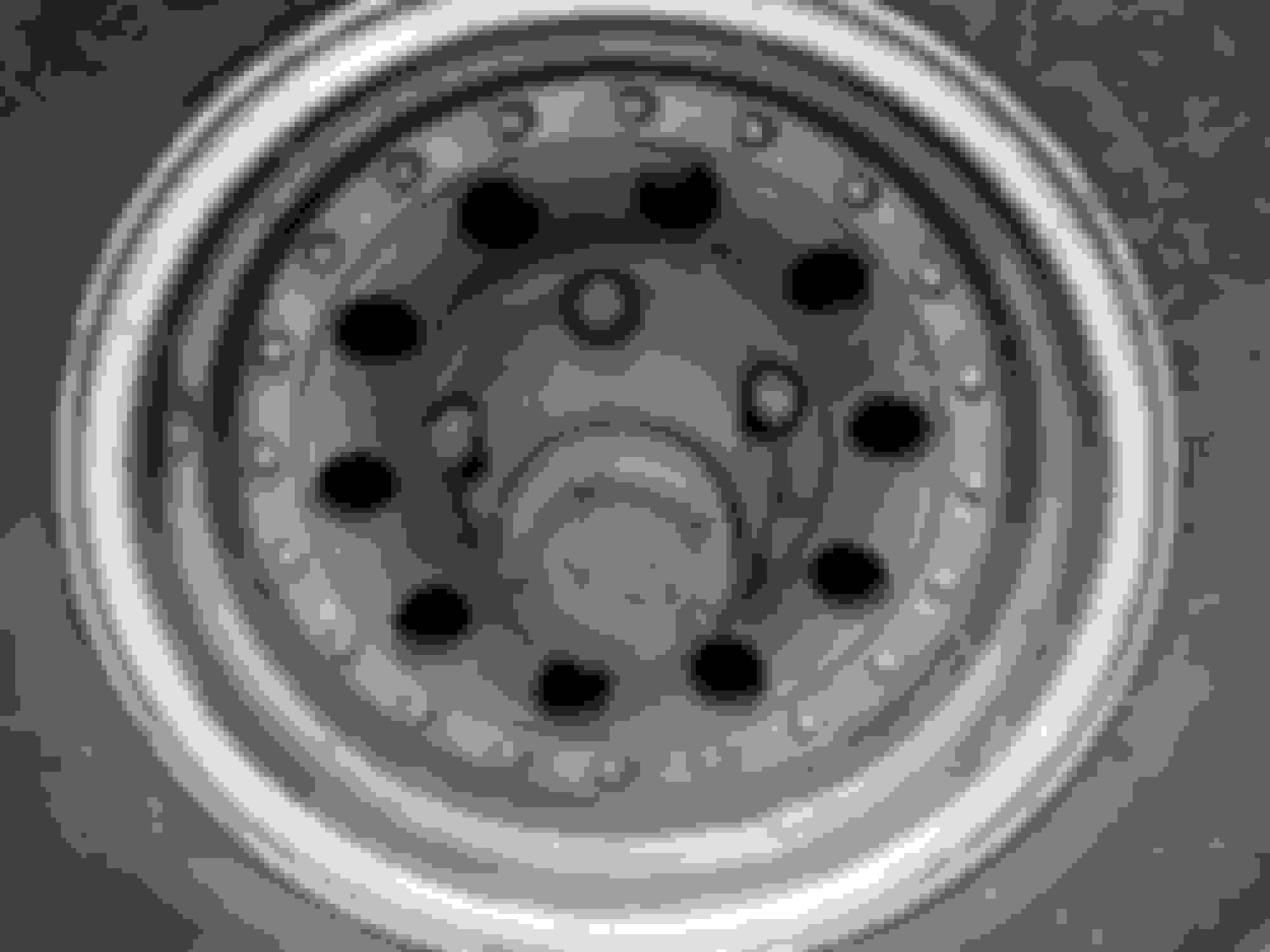
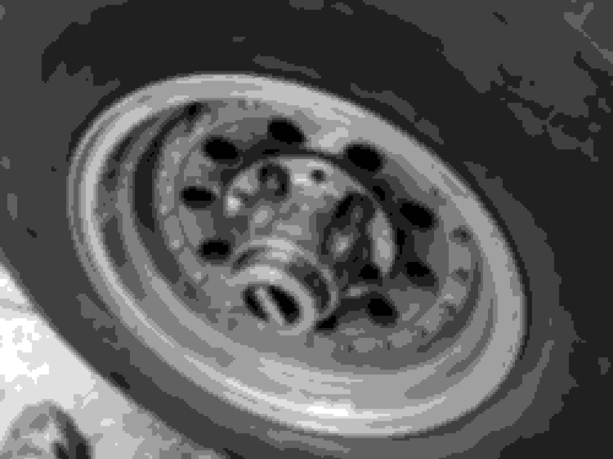
Before: This is how my wheel looked when I was about to start, a lot of brake dust and grease escaping from the hub.
After: Tire and all, ready to roll... like a boss!.
Well, congrats! you just rebuilt most of your front end, expect trouble free driving from these parts for a long while! leave a comment! time for some reps.! .
Sure, it's a nice add-on to my info Side, if someone adds the info to work on the steering linkages and suspension it would truly be a complete rebuild.
That is a good write up Encho! I am hopefully going to be doing this shortly on the Zebra. New ball joints and u joints for me tho. Also for some people might get confused, but in 93 (I think) they switch from wedge calipers to bolt on.
My bad Encho. I was reading this on my phone at the time. I was waiting for my delicious dinner to arrive at the restaurant, so the text was a little small.
I had wanted Warn Premiums too, but could only get Milemarker Hubs locally.
I would have bought them from Amazon in your place Edge, they were nicely priced, but for me it made no sense waiting (and paying) for international shipping.
Do you think most of this applies to 78 also? I think eventually i need new brakes and i know i need the driverside ball joint but i was planning to have a shop do it cause i didn't like my odds of not screwing it up. From your pictures though manual hubs don't look all that bad, I may be mistaken cause i have never seen them pulled apart in real life.
That is a good write up Encho! I am hopefully going to be doing this shortly on the Zebra. New ball joints and u joints for me tho. Also for some people might get confused, but in 93 (I think) they switch from wedge calipers to bolt on.
Yes Brett, 1993 was the last year for the wedge style pins....
1994 was the first year for the 2-13mm bolts.....
Excellent write up. Could do mine with all the detailed instructions you gave. I don't need to, but when I do, I will come here. Except I already have Warn hubs on mine.

 01-05-2012, 10:05 PM


 .
.


 I was reading this on my phone at the time. I was waiting for my delicious dinner to arrive at the restaurant, so the text was a little small.
